
Grand Hotel hairpin
- FE Gen4 reference
- 41 km/h
- DGR P1
- 50 km/h
+9 km/h at the apex

DGR / ENGINEERING & PERFORMANCE
Electric power, used to create grip. DGR explores how powered downforce, lower mass and efficient aerodynamics can change the performance of a racing car.
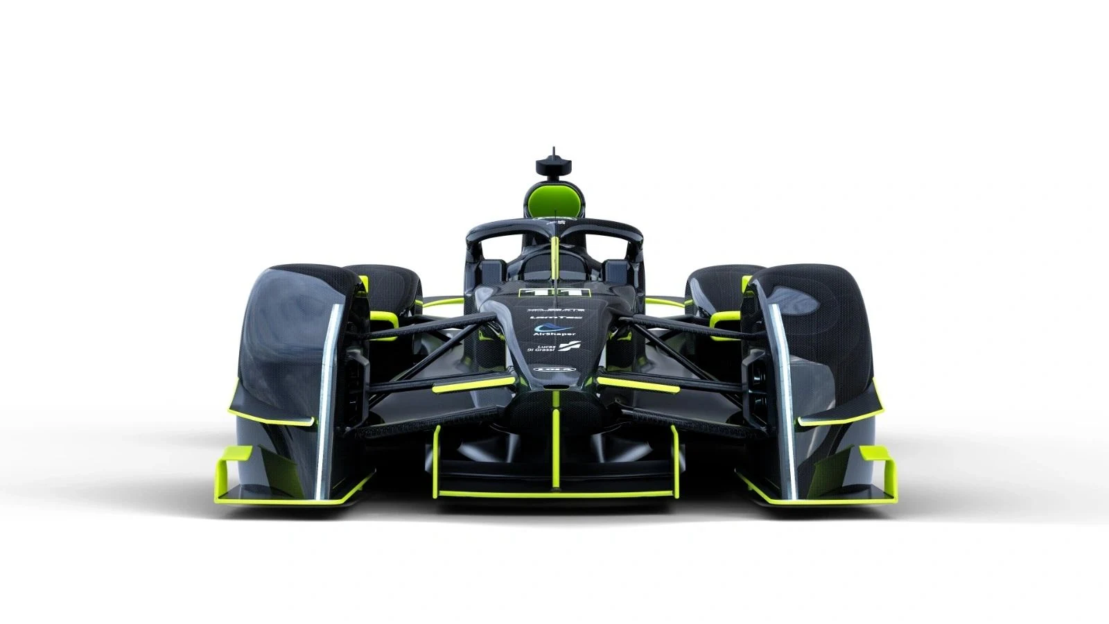 CONCEPT RENDER / 01
01 / MONACO · TRACK STUDY 1
Start with the FE Gen4 simulation. Add the DGR ideas one by one to see where the time comes from. Select a configuration to explore the model.
SIMULATED LAP TIME / LOWER IS FASTER
P4 · Full qualifying concept
MODEL ESTIMATE · ±2 s
Combine powered downforce, 700 kW and the lighter qualifying setup with the lower bodywork drag estimated by CFD.
−19.0 s versus the FE Gen4 simulation
Recorded F1 lap reference in the study, rounded. Shown for context; DGR times are simulations.
Study dated 23 October 2025. The model isolates the main concept changes; secondary mechanical differences and detailed setup optimisation are excluded. The 888 kg P3/P4 values are simulation inputs for qualifying, not a declared race-car weight.
Read the method & results · pp. 9–1002 / WHERE THE TIME IS FOUND
+33 km/h
Average simulated apex-speed gain for DGR P1 over FE Gen4. Same 600 kW motor power. Same 1,088 kg model mass. The change is powered downforce.
+9 km/h at the apex
+29 km/h at the apex
+48 km/h at the apex
THE DESIGN PRINCIPLES
Swordfish Aero
Covered wheels and streamlined bodywork target lower drag. The Run 03 CFD report gives a drag coefficient of 0.475 at 180 km/h for the analysed geometry.
Variable Dynamic Downforce
The study packages two 30 kW fans and models approximately 15 kN of total downforce around the lap. Fan contribution reduces as bodywork downforce rises with speed.
Modular Battery System
The modular battery concept allows the study to explore a 200 kg reduction for qualifying. In the model, that step reduces the lap from 63.8 to 59.8 seconds.
Electric Architecture
The model explores 600 kW and 700 kW of motor deployment, alongside the separate powered-downforce system. Further scenarios trade motor power for lower energy consumption.
THE AERODYNAMIC FOUNDATION
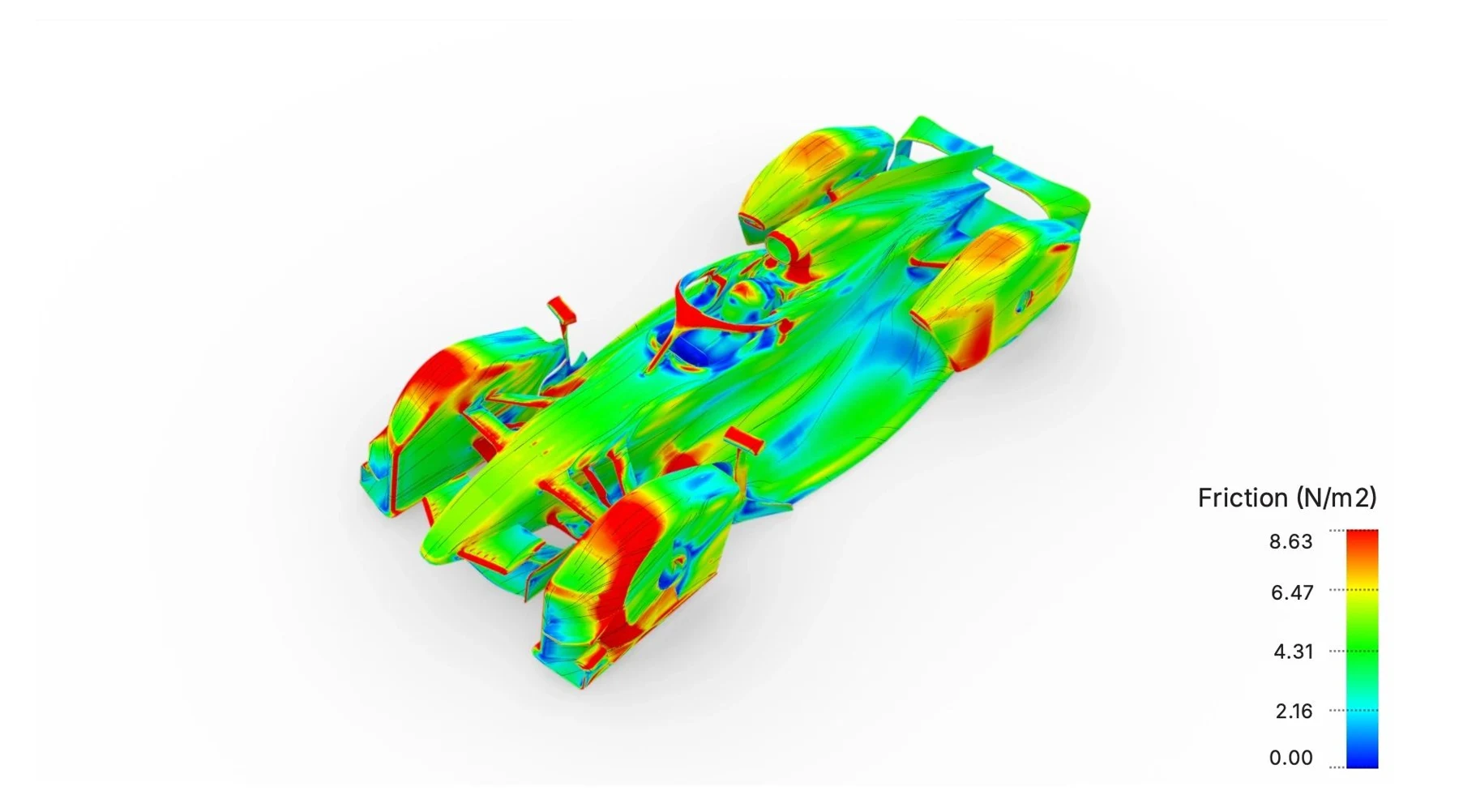
The AirShaper Run 03 report examines the bodywork at 50 m/s (180 km/h), using a moving ground, rotating wheels and a mesh of 110 million cells. It provides the aerodynamic evidence behind the concept’s lower-drag geometry.
Blockage-corrected coefficients for this CFD run. Negative Cl indicates downforce. This bodywork analysis is separate from the track model’s 15 kN total-downforce assumption.
CFD report · coefficients, p. 10ANOTHER WAY TO USE THE ADVANTAGE
Electric power can create grip as well as acceleration. That opens a different trade-off between speed and energy.
In a separate reduced-power scenario, the study estimates roughly 20% less total lap energy at a similar lap time to its FE Gen4 reference. The calculation includes an allowance for the powered-downforce system.
Energy analysis & assumptions · pp. 18–20less lap energy at comparable pace
A different configuration from the 59.5 s qualifying case. The estimate holds fan-system energy constant; the report notes that slower laps may require more, reducing the saving.
EXPLORE THE EVIDENCE
Read the original reports for the model inputs, methods, assumptions and full results. The studies define the concept’s potential and the questions for future physical validation.
THE PEOPLE BEHIND THE CONCEPT
DGR / THE NEXT CONVERSATION
Engineering, technology and project enquiries.